
Making a hexel effect
I’ve been trying to re-learn webGL lately. To get myself started, I’ve been trying to implement some simple visual effects as fragment shaders. In this post I’m going to be detailing how I made a hexel effect.

The finished thing
This is the finished project. The slider under every canvas lets you control the polygons’ side lengths. You can find the source code here.
Making a pixel shader
The first step was to try making a pixel shader. You can see the final product below.
Pixel Filter
The way webGL works is by specifying two shaders, a vertex shader and a fragment shader. The vertex shader allows one to perform transformations on a per-vertex basis. The fragment shader is used to color in “fragments” of a surface being rendered. The effects I want to implement here will be implemented in the fragment shader.
To pass the source image into the shaders, I copy the image onto a texture which can be accessed by the shaders.
The fragment shader is a function that will recieve coordinates in the range \((0, 1) \times (0, 1)\). If all I wanted to do was display the image, I would just pass those coordinates into a function to lookup the color on the texture that corresponds to that point.
The implementation for the pixel shader is pretty basic. If we imagine the
canvas as being covered by a bunch of squares of an arbitrary length N, it’s
easy to see that for any point \((x, y)\), we can find the bottom left corner
of the square that contains it by computing
\( N * (\lfloor{\frac{x}{N}}\rfloor, \lfloor{\frac{y}{N}}\rfloor) \).
Finally to get the pixel effect we just need to make sure that every coordinate inside a given square is colored in the same. The code that does that is displayed below.
varying mediump vec2 vTextureCoord;
varying mediump vec3 vLighting;
uniform sampler2D uSampler;
uniform mediump float uPixSize;

void main(void) {
    mediump float n = max(uPixSize, 0.01) / 10.0;
    gl_FragColor = texture2D(
        uSampler, n * floor(vTextureCoord / n));
}
In the code above uSampler is the texture passed in, and uPixSize is the
value of the slider.vTextureCoord is the coordinates of the fragment we want
to act on. We transform the uPixSize value slightly for better
results.
Making a hexel shader
To make a hexel shader we want to generalize the method we used for the pixel shader. What we want to have is a fast way where, given some coordinates, I want to find out what hexagon it belongs to. Then I can just use the pixel value of some point in that hexagon mapped to the texture to make the entire hexagon have the same color. Formalizaing this idea, the problem we need to solve is:
In a space covered by tesslating hexagons, given a point \((x, y)\) find
the center of the hexagon containing that point.
Since I need this solution to be fast, and since branching in GPUs is expensive, it’s not feasible to calculate and check the center of every hexagon that is within my coordinate space.
I wanted to reuse the general idea from the pixel shader somehow, so I wanted to first cover the hexagons with rectangles. I came up with the following idea:
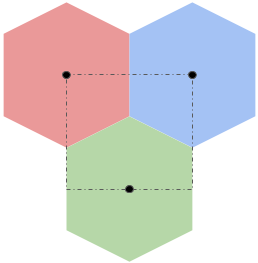
If we could cover an entire space with this pattern, then for any given pixel we could quickly lookup which rectangle we were in and then we just have to determine one of three possible centers that correspond to well known points on the rectangle’s perimeter. Given a point \((x, y)\), and the height and width of the rectangle as \(W\) and \(H\), we can then find these points as:
- The top left corner \((W * \lfloor{\frac{x}{W}}\rfloor, H * \lfloor{\frac{y}{H}}\rfloor) \).
- The top right corner \((W + W * \lfloor{\frac{x}{W}}\rfloor, H * \lfloor{\frac{y}{H}}\rfloor) \).
- The center of the bottom edge \((\frac{W}{2} + W * \lfloor{\frac{x}{W}}\rfloor, H + H * \lfloor{\frac{y}{H}}\rfloor) \).
This approach doesn’t quite work, since hexagons don’t tesslate when grouped into triples like these. With some ammendment to my original idea, I arrived at:
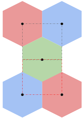
Where the bottom half is just the top half but flipped.
This also doesn’t quite tessalate, but if you let them overlap by half a hexagon, the rectangles will tessalate, and if you “merge” the overlapping hexagons then the hexagons also tessalate. In the picture below, the overlapping hexagons are given a purple-ish color.
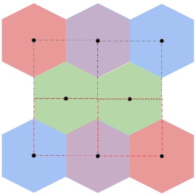
For now let’s focus on the first image, and we’ll worry about the flipping and stuff later.
To do that, we need to calculate \(W\) and \(H\) for the rectangle. Let’s look at what we’re working with again.
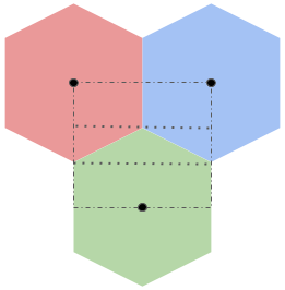
To calculate \(H\), we first look at the rectangle as being divided into three horizontal strips. The first strip starts at the top of the rectangle and extends down until it touches the top of the green hexagon. The second one starts at the top of the green hexagon and continues down until the start of the vertical edge of the green hexagon. The last strip starts at the top of the vertical edge of the green hexagon and continues down to the bottom of the rectangle.
Since a hexagon can be divided into 6 equilateral tessalating triangles, we know that the sum of the heights of the first two strips is \(n\). The last strip starts at the vertical edge of the green triangle and continues till the center of the hexagon which means that the height of this strip must be \(\frac{n}{2}\). Thus, \(H = \frac{3 * n}{2}\).
To calculate \(W\) we just need to find the width of a hexagon, since the rectangle’s is half the width of the red hexagon plus half the width of the blue hexagon. The easiest way to do this is to look at the green triangle formed by the second rectangle strip. This triangle has two sides of length \(n\) and the angle formed by those two sides is \(\frac{2\pi}{3}\). Using some simple trignometery, we can work out that the third side has length \(\sqrt{3}n\) so \(W = \sqrt{3}n\).
Whew, so after all that work, we can finally figure out which rectangle each pixel belongs to. Now we just have to figure out which hexagon it belongs to. To make our lives simpler, for each pixel, once we find which rectangle we’re in, we can perform a coordinate transform to make it so that the “origin” is the top left corner of the containing rectangle. Then, when have the coordinates we want to lookup in the texture, we just need to undo this transform. This also hints that when we start looking at the cases where we need the flipped version of the tesslating hexagons above, we could use the same technique and perform another coordinate transform to invert the y-axis temporarily. This means that the work we do below will be applicable to all coordinates in our space!
For a given coordinate (after being appropriately) transformed we can consider which of the three strips it belongs to. It’s easy to find out which strip each coordinate belongs to by testing it against the \(y\) coordinates of the top and bottom of each strip.
In the first strip, we know that if the coorindate’s \(x\) value is less than \(\frac{W}{2}\), then it belongs to the red triangle. Otherwise, it belongs to the blue triangle.
In the third strip, all coordinates map to the green triangle.
The second strip is a little more involved, so let’s test what we already have.
varying mediump vec2 vTextureCoord;
varying mediump vec3 vLighting;
uniform sampler2D uSampler;
uniform mediump float uPixSize;

// sign(sign(a - b) + 1) -> 1 if a >= b 0 if a < b
mediump float isGEq(float a, float b) {
     return sign(sign(a - b) + 1.0);
}

void main(void) {
     mediump float n = max(uPixSize, 0.01) / 10.0;
     mediump float halfn = n / 2.0;

     mediump float sqrt3 = 1.732;

     mediump float W = sqrt3 * n;
     mediump float halfW = W/2.0;

     mediump float H = 3.0 * halfn;

     mediump float xidx = floor(vTextureCoord.x / W);
     mediump float yidx = floor(vTextureCoord.y / H);

     // Get top left corner of bounding square
     mediump vec2 o = vec2(
          W * xidx, H * yidx);

     // transform coordinates to make square begin at origin
     mediump vec2 t = vTextureCoord - o;

     // Hexagon targets in transformed space
     mediump vec2 vertA = vec2(0.0, 0.0);
     mediump vec2 vertB = vec2(W, 0.0);
     mediump vec2 vertC = vec2(halfW, H);

     // Additional "target" for debuggging
     mediump vec2 vertInvalid = vec2(-1.0, 0.0);

     mediump float xLeHalfW = isGEq(halfW, t.x);
     mediump float yLehalfN = isGEq(halfn, t.y);
     mediump float yGeN = isGEq(t.y, n);

     // output to sampler
     mediump vec2 hex =
          yLehalfN * (
              xLeHalfW * vertA +
              (1.0 - xLeHalfW) * vertB) +
          yGeN * vertC +
          (1.0 - yLehalfN) * (1.0 - yGeN) * vertInvalid;

    if (hex == vertA)
        gl_FragColor = vec4(1.0, 0.0, 0.0, 1.0);
    else if (hex == vertB)
        gl_FragColor = vec4(0.0, 0.0, 1.0, 1.0);
    else if (hex == vertC)
        gl_FragColor = vec4(0.0, 1.0, 0.0, 1.0);
    else
        gl_FragColor = vec4(0.0, 0.0, 0.0, 1.0);
}
This code attempts to color each hexagon with a constant color. I tried to implement most of the logic without branching for high performance, but since this is just a debugging tool, I cheated a bit towards the end.
What we’re seeing here looks about right, with the exception of the fact that in webGL, the y-axis is flipped, so it’s upside down. That doesn’t really matter to us, so I’ll let it remain upside down. What we want now is for the black strips to be replaced with the pattern from the middle strip in the diagram above (the one containing a green triangle).
In the second strip things are a little tricky. If the coorindate’s \(x\) value is less than \(\frac{W}{2}\), then we need to test if the coordinate is above or below the diagonal line formed by the edges of the red and green hexagons. Assuming the top left corner of the second strip is \((0, 0)\), this line is modeled by \(y = \frac{\frac{W}{2} - x}{\sqrt{3}}\). Similarly the blue-green edges line is modelled by \(y = \frac{x - \frac{W}{2}}{\sqrt{3}}\).
Throwing that into our testing code, we get:
...unchanged
    mediump float yt = t.y - halfn;
    mediump float xt = (t.x - halfW) / sqrt3;
    mediump float xnt = (halfW - t.x) / sqrt3;

    mediump float xntGeYt = isGEq(xnt, yt);
    mediump float xtGeYt = isGEq(xt, yt);

    // output to sampler
    mediump vec2 hex =
        yLehalfN * (
             xLeHalfW * vertA +
             (1.0 - xLeHalfW) * vertB) +
        yGeN * vertC +
        (1.0 - yLehalfN) * (1.0 - yGeN) * (
             xLeHalfW * (
                xntGeYt * vertA +
                (1.0 - xntGeYt) * vertC) +
             (1.0 - xLeHalfW) * (
                xtGeYt * vertB +
                (1.0 - xtGeYt) * vertC));

   if (hex == vertA)
        gl_FragColor = vec4(1.0, 0.0, 0.0, 1.0);
    else if (hex == vertB)
        gl_FragColor = vec4(0.0, 0.0, 1.0, 1.0);
    else if (hex == vertC)
        gl_FragColor = vec4(0.0, 1.0, 0.0, 1.0);
...
Finally, we just need to add in a bit of code to flip the y-axis for every other row of rectangles. While we’re at it, we might as well also undo the coordinate transforms and lookup the real pixel values. This gives us the final code and end product:
varying mediump vec2 vTextureCoord;
varying mediump vec3 vLighting;
uniform sampler2D uSampler;
uniform mediump float uPixSize;

// sign(sign(a - b) + 1) -> 1 if a >= b 0 if a < b
mediump float isGEq(float a, float b) {
    return sign(sign(a - b) + 1.0);
}

void main(void) {
    mediump float n = max(uPixSize, 0.01) / 10.0;
    mediump float halfn = n / 2.0;

    mediump float sqrt3 = 1.732;

    mediump float W = sqrt3 * n;
    mediump float halfW = W/2.0;

    mediump float H = 3.0 * halfn;

    mediump float xidx = floor(vTextureCoord.x / W);
    mediump float yidx = floor(vTextureCoord.y / H);

    // Get top left corner of bounding square
    mediump vec2 o = vec2(W * xidx, H * yidx);

    // transform coordinates to make square begin at origin
    mediump vec2 t = vTextureCoord - o;

    // Hexagon targets in transformed space
    mediump vec2 vertA = vec2(0.0, 0.0);
    mediump vec2 vertB = vec2(W, 0.0);
    mediump vec2 vertC = vec2(halfW, H);

    mediump vec2 vertInvalid = vec2(-1.0, 0.0);

    // pattern alternates every other row
    if (mod(yidx, 2.0) != 0.0) {
        t.y = H - t.y;
    }

    mediump float xLeHalfW = isGEq(halfW, t.x);
    mediump float yLehalfN = isGEq(halfn, t.y);
    mediump float yGeN = isGEq(t.y, n);

    mediump float yt = t.y - halfn;
    mediump float xt = (t.x - halfW) / sqrt3;
    mediump float xnt = (halfW - t.x) / sqrt3;

    mediump float xntGeYt = isGEq(xnt, yt);
    mediump float xtGeYt = isGEq(xt, yt);

    // output to sampler
    mediump vec2 hex =
        yLehalfN * (
             xLeHalfW * vertA +
             (1.0 - xLeHalfW) * vertB) +
        yGeN * vertC +
        (1.0 - yLehalfN) * (1.0 - yGeN) * (
             xLeHalfW * (
                xntGeYt * vertA +
                (1.0 - xntGeYt) * vertC) +
             (1.0 - xLeHalfW) * (
                xtGeYt * vertB +
                (1.0 - xtGeYt) * vertC));

    if (mod(yidx, 2.0) != 0.0) {
        hex.y = H - hex.y;
    }

   hex += o;
   gl_FragColor = texture2D(uSampler, hex);
}
Hexel Filter
Conclusions
Overall, this was a great exercise to re-learn webGL. I learned a ton about how to write code without branching, and also about debugging webGL. Obviously what I have here isn’t perfect, but it’s good enough for me to want to put it down and move on to other challenges.